Link assembly-trailing rear suspension change
Link assembly-trailing rear suspension change was created by cjj
Posted 12 years 7 months ago #48957
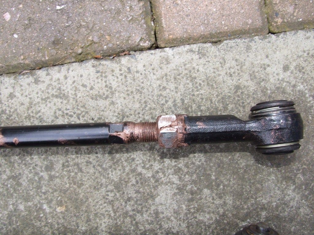
The Link assembly-trailing rear suspension, as it is known in the parts catalogue is part of the suspension and helps keep the rear hub parallel when the wheel moves up and down during suspension travel. This part is responsible for keeping correct camber and toe in/out, along with other components.
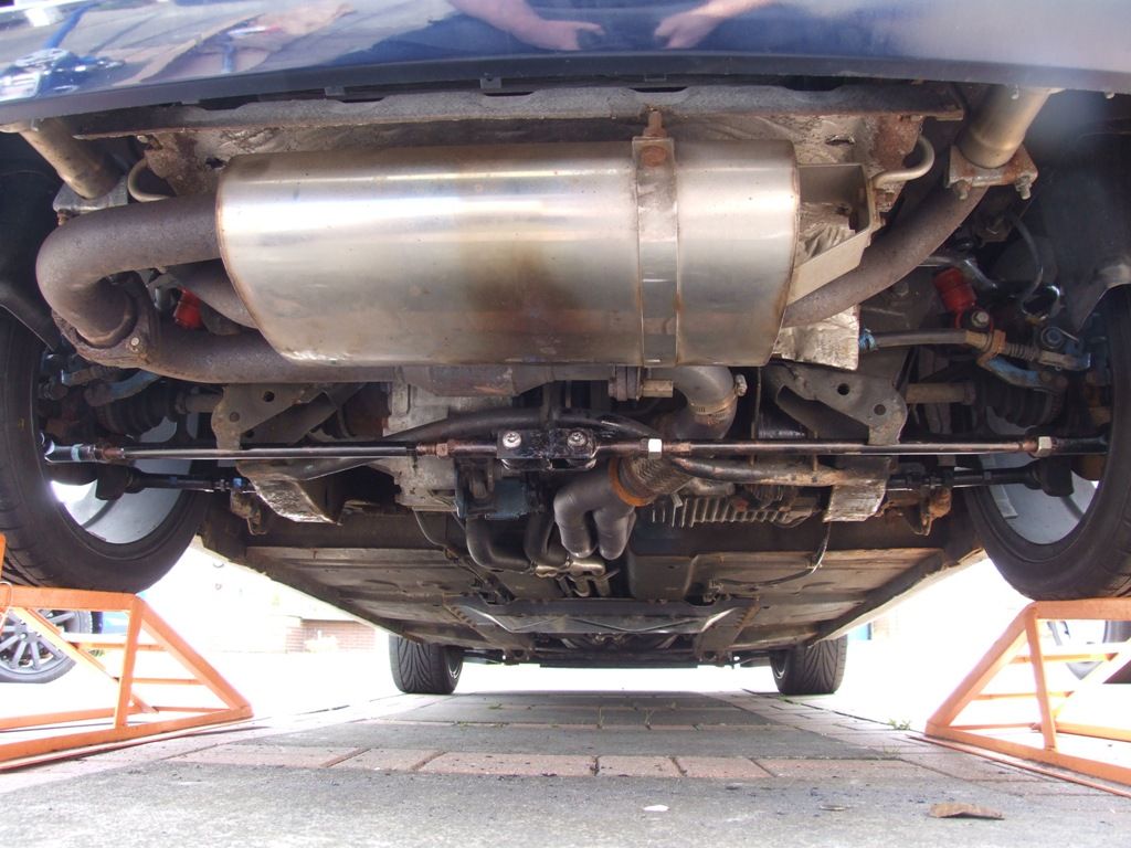
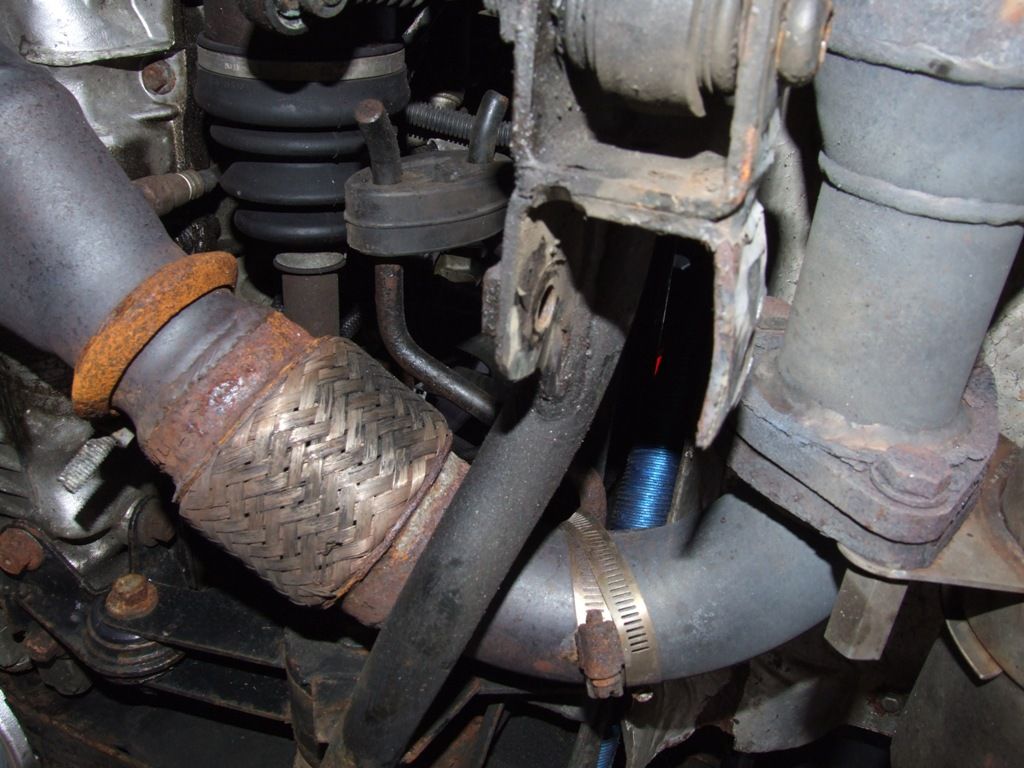
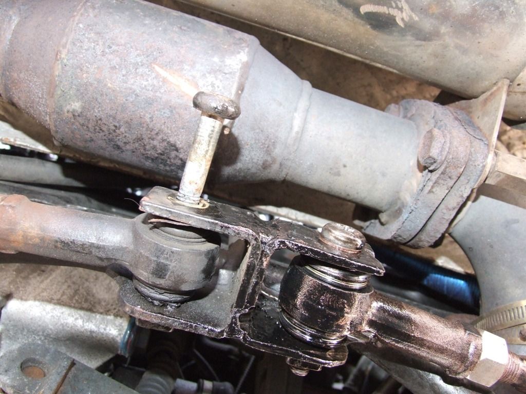
The two rods come from the bottom of the hubs and connect to a bracket at the rear bottom centre of the subframe.
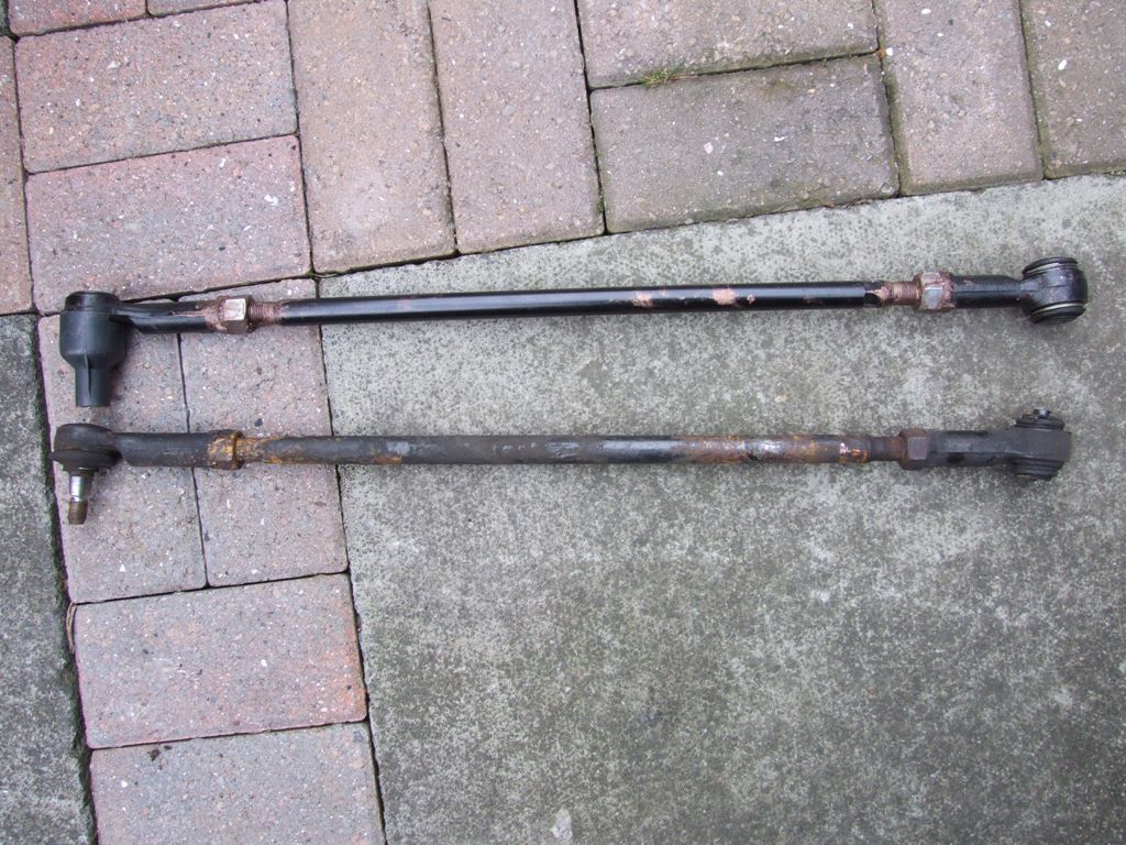
These are the rods we will be changing (the pic shows new ones fitted).
So, why would we need to change the rods?
As with most suspension components, they wear. The rubber bushes at the end become soft and increased play results in movement of the rear hub and the car will wander and feel as though you are driving on ice. In my case the 4 wheel laser alignment was being carried out when they discovered they could not loosen the locknuts and therefore couldn’t adjust the suspension to the correct settings.
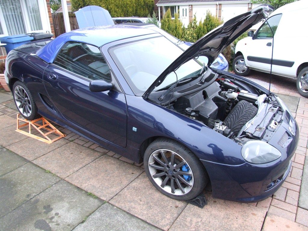
As we have discovered that we that we need to change the arm, we now need to raise the rear end up off the ground. For this job I found reversing it up onto the ramps and then taking the weight of the car on the subframe with a jack the best way to go. The reason for this is that the wheel and hub would no longer be held in place by the rod and if the weight of the car was on the wheel it may stress the other components as it tried to move. Likewise, just jacking the chassis up could stress the components as the wheel will be hanging in mid air. With the car on the ramps, jack the chassis up on the side you will be working on, just enough to take the weight off the suspension.
The usual Health and Safety stuff applies.
Only work on level ground using correct equipment, such as a jack and axle stands of the correct rating. Also chock the front wheels as the handbrake won’t work with the rear wheels off the ground.
The part numbers for the arms are RGD000620 (RHS) and RGD000630 (LHS).
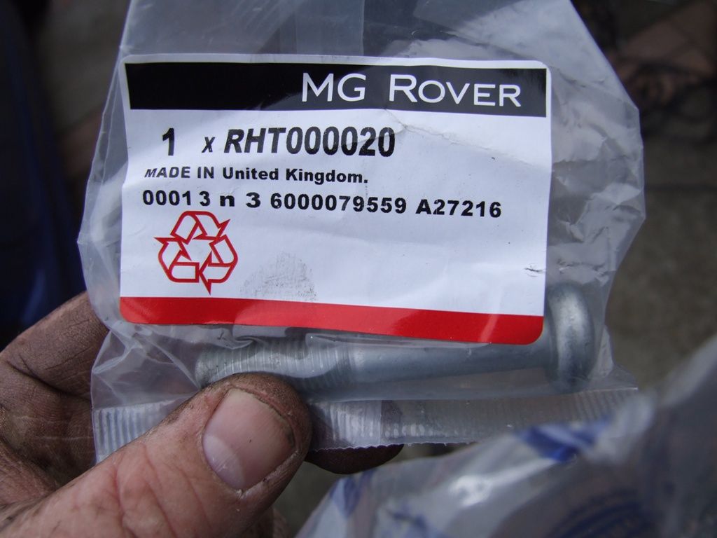
The torx centre bolts are RHT000020 and are “Bolt-torx-pan - M10 x 65”. You will need one per side.
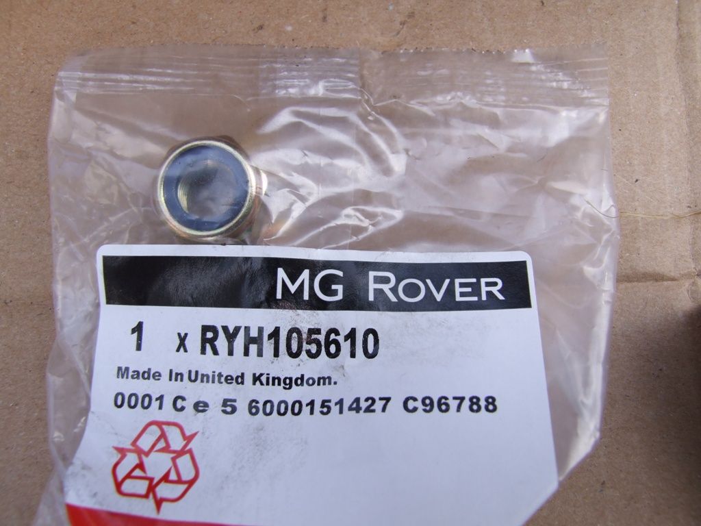
The nut for the hub end is RYH105610 and again, one per side.
When I received my new rods I disassembled them and introduced them to a good helping of Copper Grease. This should help prevent them from seizing in the future. Once the rods are fitted it will be difficult to Copper grease all of the threads, so now would be the ideal time.
The rods are pretty easy to access once the car is up in the air and, in theory, should be easy to change. Mine were not as one had rusted in place. Hopefully you won’t have that problem, but I will take you through what I did just in case.
Treat the bolts and nut to a good spray of release oil and leave overnight. This will help if theye have been on a long time. You could also wire brush the threads to remove any rust or dirt to make it easier to remove.
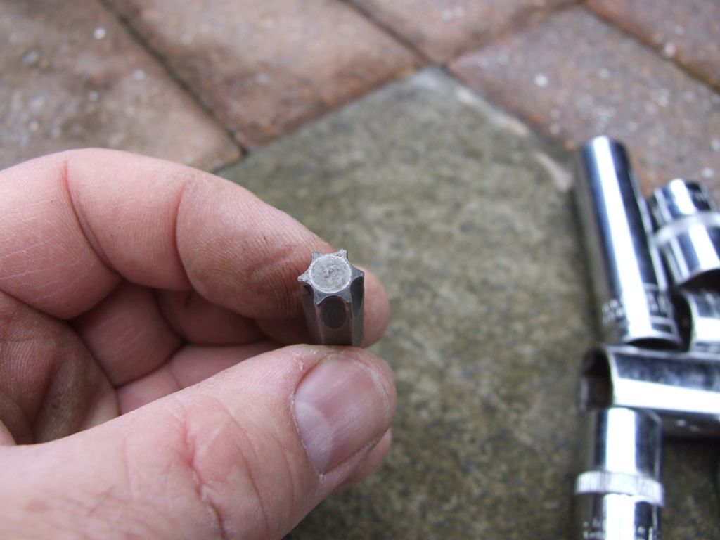
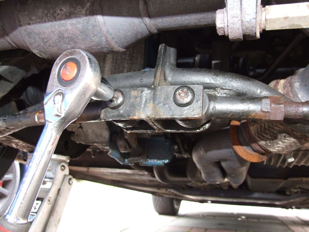
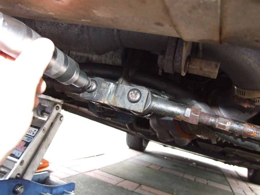
Using a T50 Torx bit, loosen the centre torx bolt.
If you are lucky, you might be able to do it with a normal ratchet
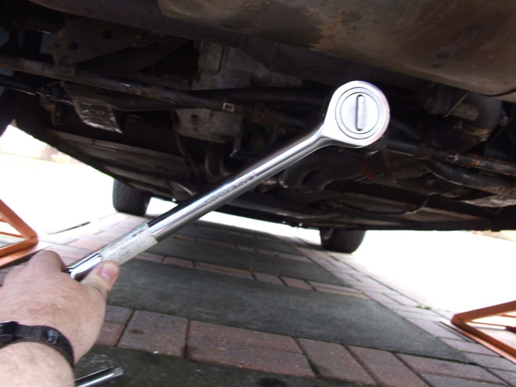
Or you may need extra leverage from a longer ratchet or bar
Or an impact driver
Either way, try to avoid rounding off/stripping the torx bit. You may need to clean out the torx hole or hammer the bit in to get a better grip.
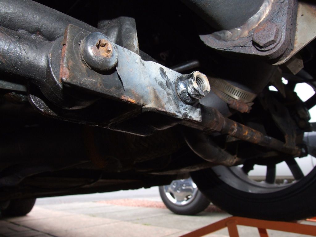
Guess what. My bolt rounded off.
This was an unusual one and turned out to be due to the bolt rusting to the inner part of the rod end. If this happens things start getting a bit complicated.
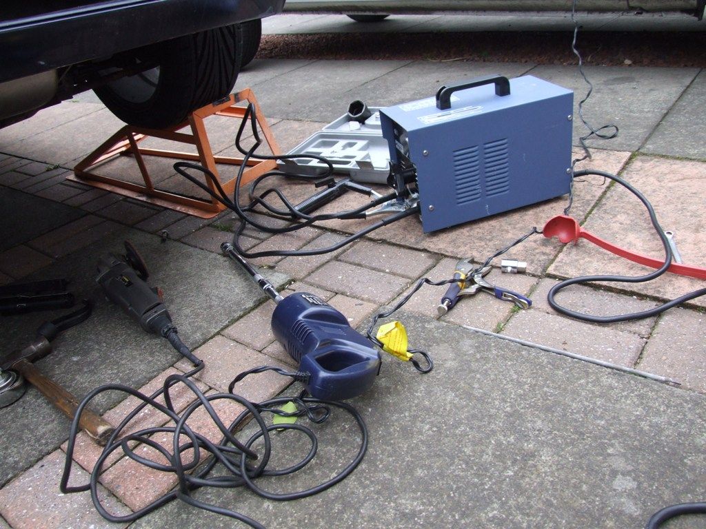
I ended up welding a nut onto the end of the bolt and using a socket. It was still very slow going and I had to cut it out eventually.
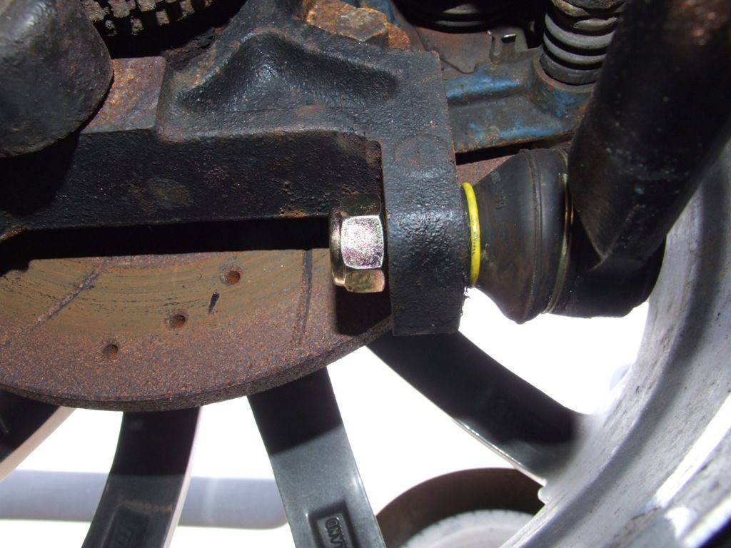
Once the bolt is free, remove the nut holding the other end of the rod to the hub.
You can now either use a ball joint splitter to break the tapered joint, or, if you aren’t reusing the rod, just hammer the threaded portion until it releases.
Now remove the centre torx bolt and swing the rod clear.
You will probably have a bit of fiddling on your hands fitting the new one, but it is best to put the old and new one together to try and adjust the new one to the same length.
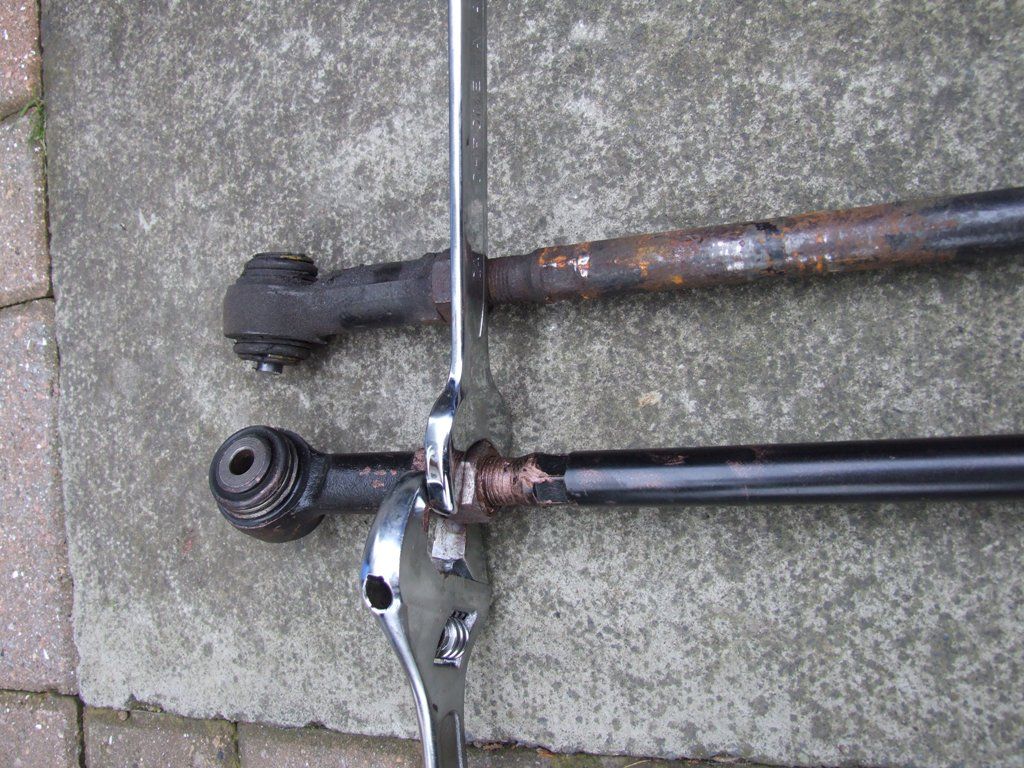
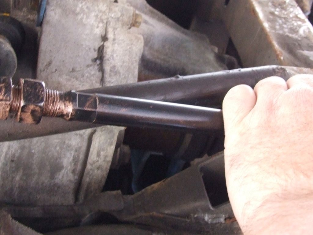
Loosen the lock nuts and wind the ends in/out to achieve the correct length. One end is a left hand thread and the other end is a right hand thread
Try to ensure that there is an equal amount of thread showing at either end when you have finished. This will ensure you have maximum adjustment left once fitted. Also leave the locknuts loose for the moment, as this will help line up the hole in the centre bracket.
While supporting the bar, push the tapered joint into place at the hub end.
Loosely place the new nut on the threaded portion just to stop it falling out.
Now offer up the centre joint to the subframe bracket. You may find that the holes don’t line up. If this is the case, grip the bar in the centre and turn it. This will lengthen or shorten the bar and will help the hole line up.
Now, place the torx bolt and fasten it up, but don’t tighten it yet.
You should now lower the jack so that the weight of the car is on the wheel.
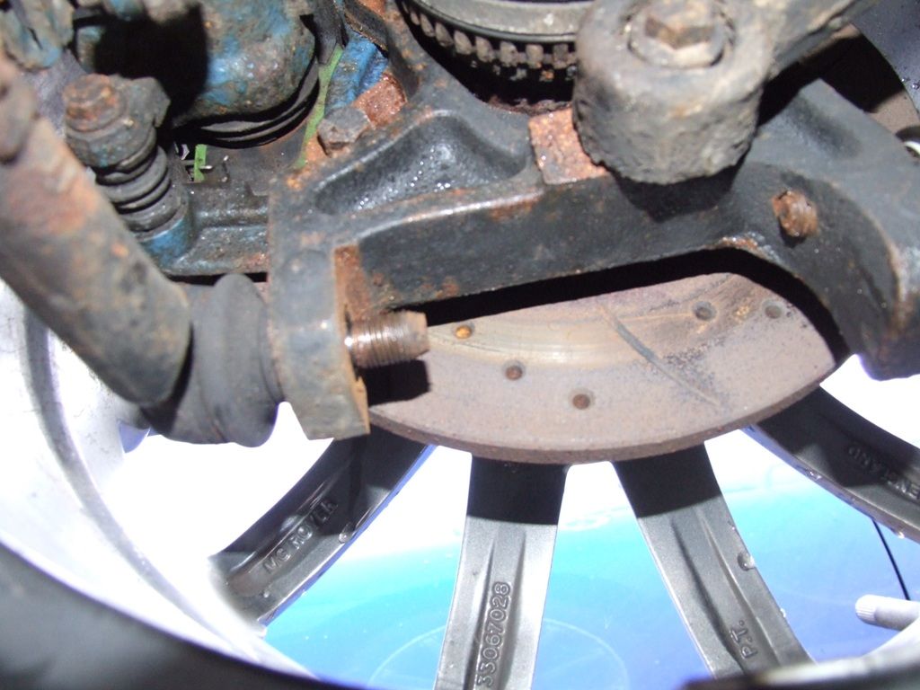
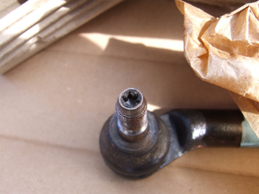
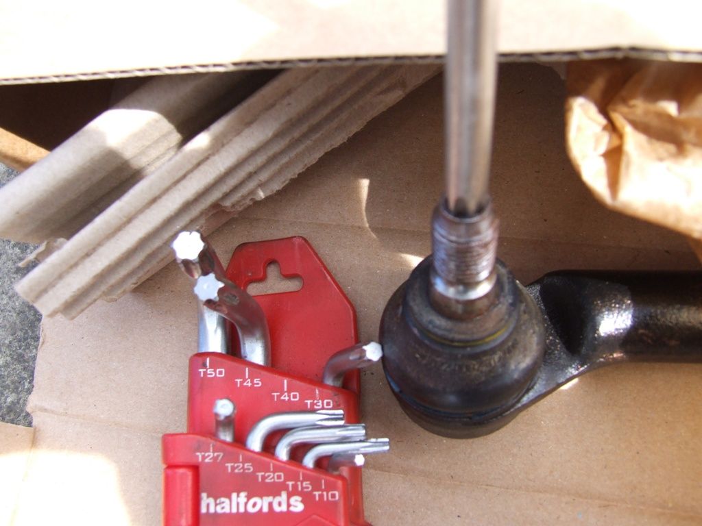
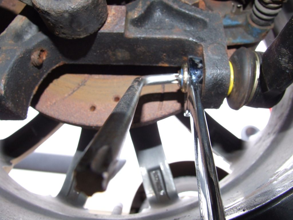
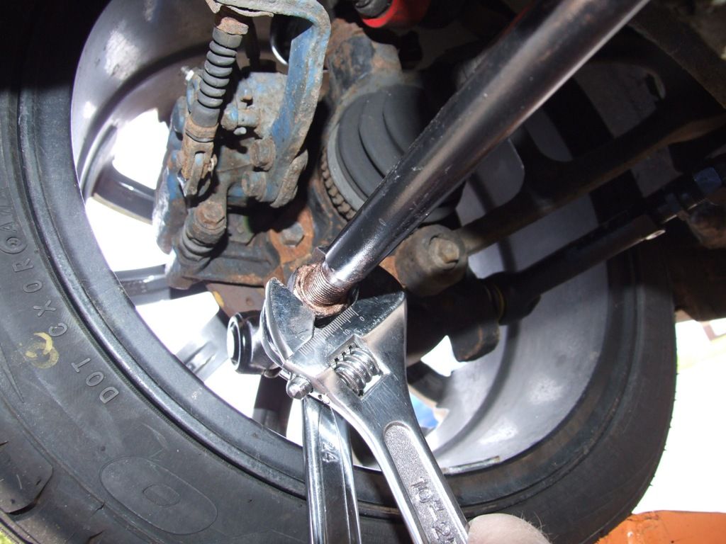
The hub end of the bar has a tapered joint which will grip the hub when tightened. Until it is tightened enough though it will just turn. To hold the joint still while you tighten the nut, there is a torx hole in the end of the thread.
The torx key needed is a T40.
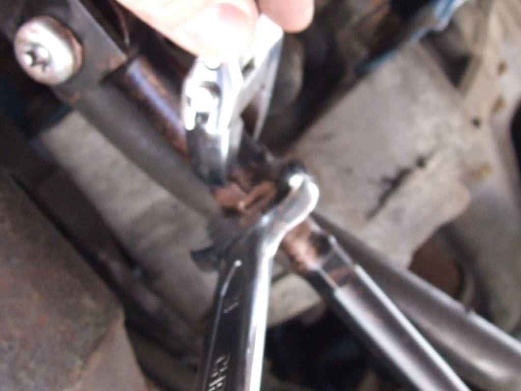
Hold the torx key in place while using a spanner to tighten the nut unto the bar end. This will stop the thread turning until the tapered joint can grip.
Tighten until the torx bit is no longer needed, but do not fully tighten.
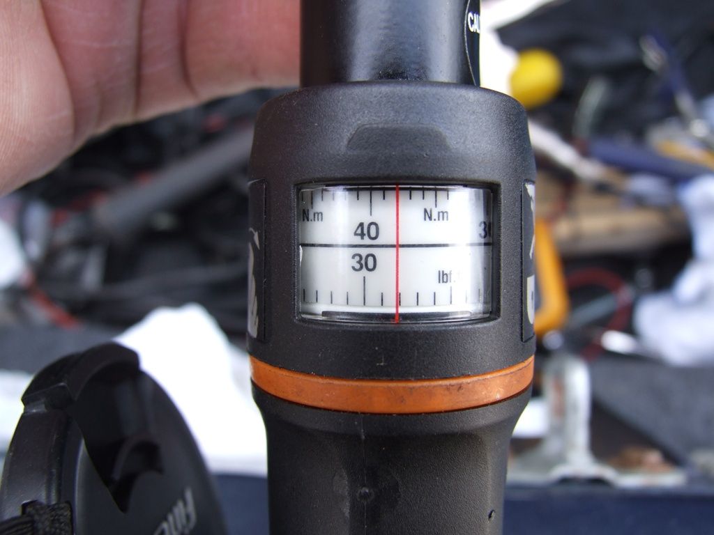
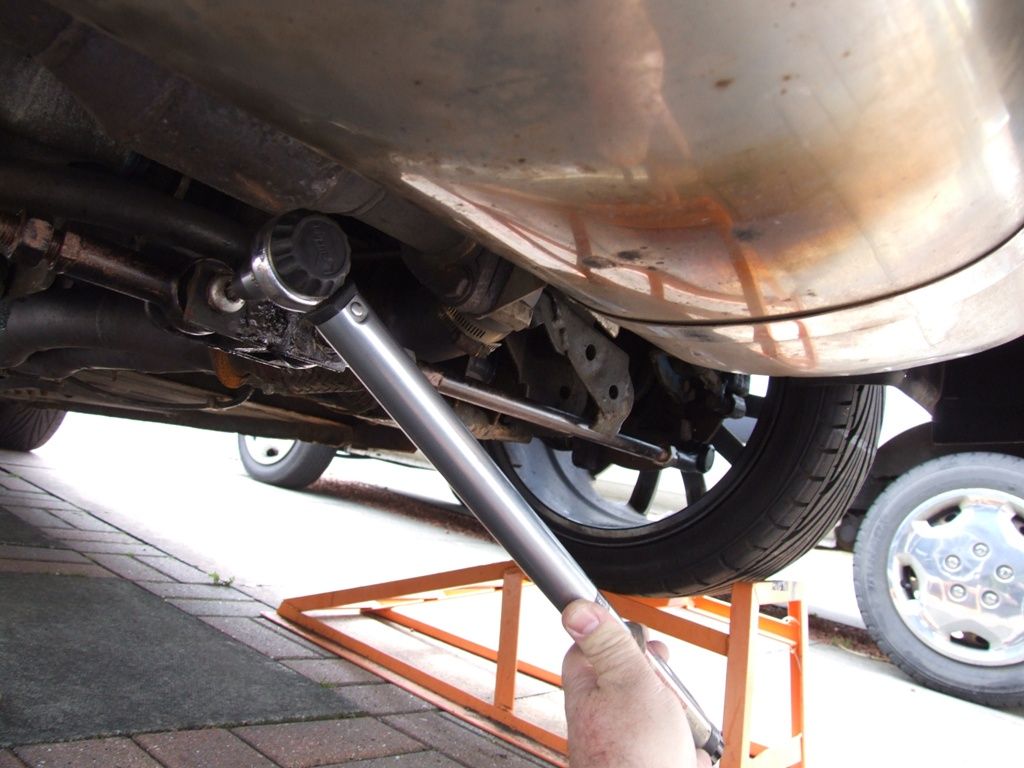
Now, set a torque wrench to 38Nm
And tighten the nut until the torque wrench clicks.
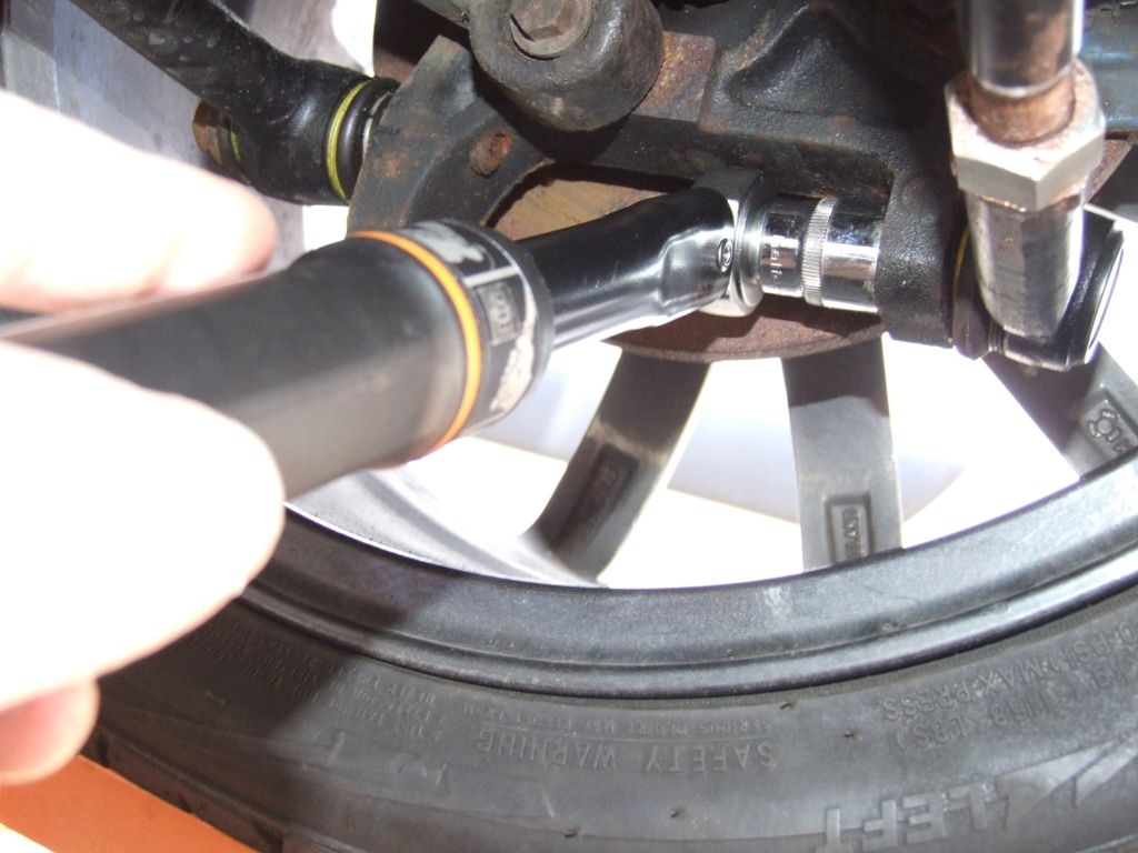
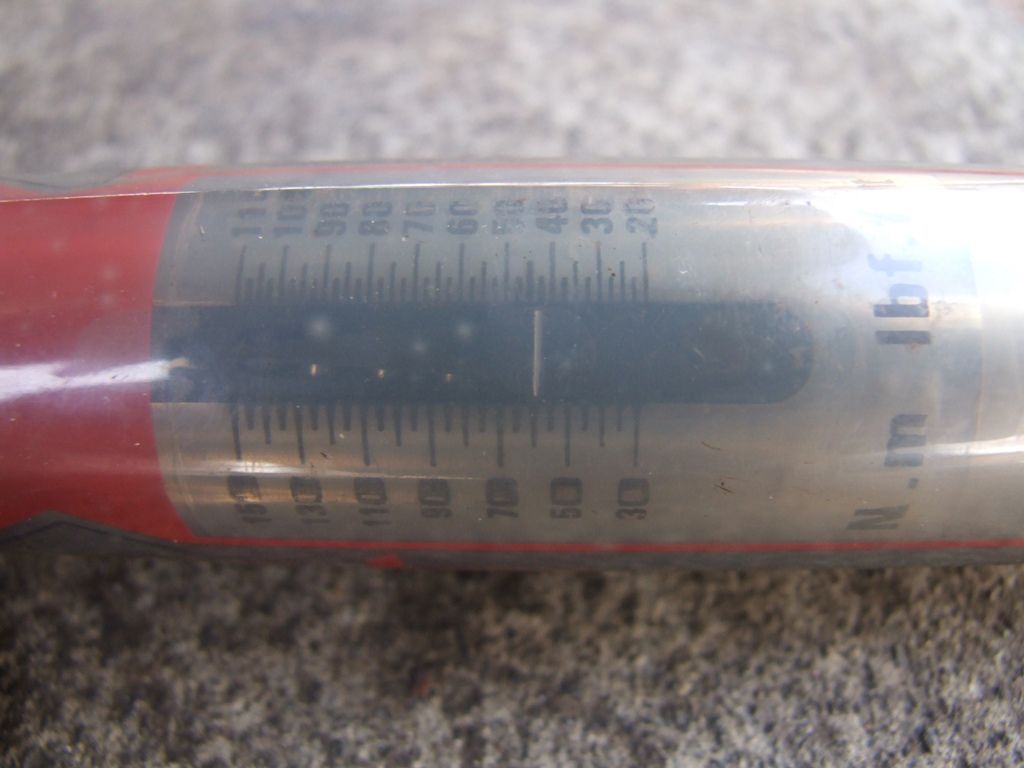
Now set a torque wrench to 60Nm
And tighten the centre torx bolt.
Finally, tighten up the locknuts.
You have now replaced the link assembly-trailing rear suspension bar. If you need to change both, the procedure is the same for both sides.
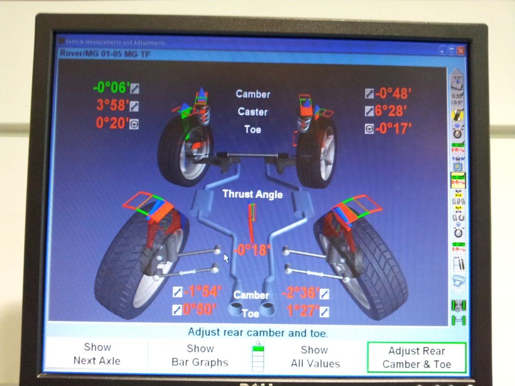
It is now time to spend some money and get the 4 wheel laser alignment done on the car. This is important as the car will handle like a drunk pig skating on ice and will effect tyre wear.
This was mine after I had done the rods.
Usual stuff applies. This how to is only a guide and you attempt these jobs at your own risk.
by cjj
Please Log in or Create an account to join the conversation.
- David Aiketgate
-
 Offline
- David
-

- mgf mk2 freestyle mpi 16" wheels, in Anthracite.
- Posts: 20353
- Thanks: 4453
Replied by David Aiketgate on topic Re: Link assembly-trailing rear suspension change
Posted 12 years 7 months ago #48958
Nice one Clive!:broon:
Have you got a photo of the screen after adjustment?
Have you got a photo of the screen after adjustment?
David
:shrug:
Please Log in or Create an account to join the conversation.
Replied by cjj on topic Re: Link assembly-trailing rear suspension change
Posted 12 years 7 months ago #48990
No, but I have a printout. Will try and digitise it.
by cjj
The following user(s) said Thank You: David Aiketgate
Please Log in or Create an account to join the conversation.
Replied by tui on topic Re: Link assembly-trailing rear suspension change
Posted 12 years 7 months ago #48993
Fantastic as always Clive :broon: Thanks for the very detailed How-To :beer:
by tui
Please Log in or Create an account to join the conversation.
Time to create page: 0.540 seconds

