
MG F/TF Front Fogs - Parts, Wiring Diagram, Installation Guides
Replied by PipL on topic MG F/TF Front Fogs - Parts, Wiring Diagram, Installation Guides
Posted 3 months 3 weeks ago #208558
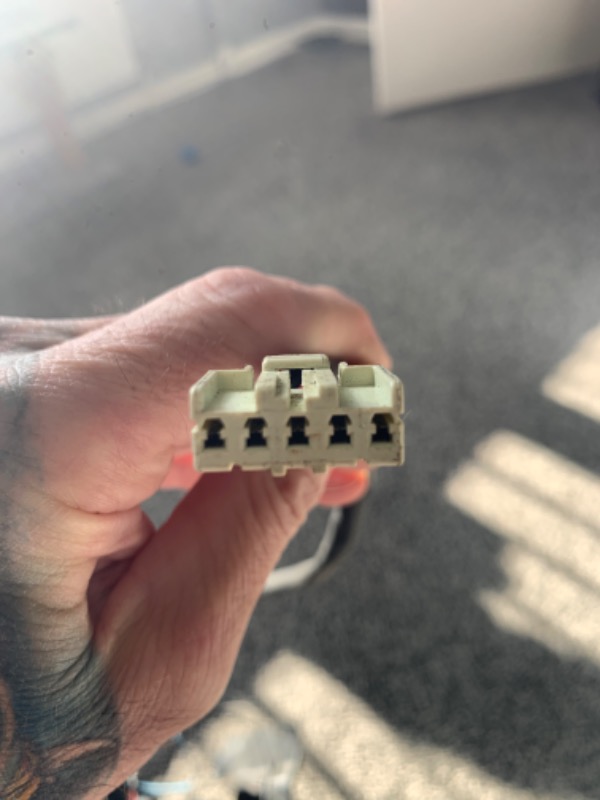
This is the mk1 loom switch connector.
this is the mk1 switch
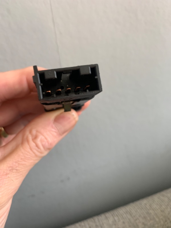
this is the mk2 switch
the locating grooves don’t match up
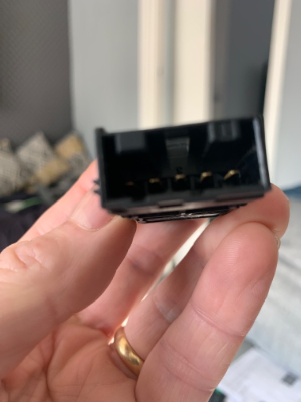
this is the mk1 switch
this is the mk2 switch
the locating grooves don’t match up
by PipL
Please Log in or Create an account to join the conversation.
Replied by PipL on topic MG F/TF Front Fogs - Parts, Wiring Diagram, Installation Guides
Posted 3 months 3 weeks ago #208559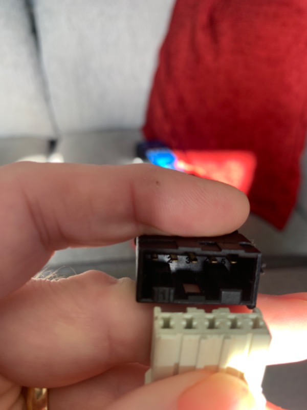
this is the mk1 switch
this is the mk2 switch
the locating grooves don’t match up
by PipL
Please Log in or Create an account to join the conversation.
Replied by Roverlike on topic MG F/TF Front Fogs - Parts, Wiring Diagram, Installation Guides
Posted 3 months 3 weeks ago #208561
Ok, I see, but you can remove locating pins on the connector with a cutter or scalpel.
However, my problem is I do not know where these 5 wires are connected in the rest of the loom, so cannot say will it work as expected.
Problem is I am not expecting 5 wires in front fogs switch, and I do not know how that switch behaves. It is possible that some other switch is used and because of that wires are rearranged. In that case you cannot just swap it to front fogs mk2 switch as internals of the switch are different.
I would measure with multimeter how nternaly both switches are made (with internal connections) and what you get on the pins of the swithes.
Last Edit:3 months 3 weeks ago
by Roverlike
Last edit: 3 months 3 weeks ago by Roverlike.
Please Log in or Create an account to join the conversation.
- Airportable
-
 Offline
- Senior MGer
-

- Posts: 2259
- Thanks: 512
Replied by Airportable on topic MG F/TF Front Fogs - Parts, Wiring Diagram, Installation Guides
Posted 3 months 3 weeks ago #208564
Can I chuck a curved ball at you? It could be that the earlier switch is latching , whereas the later could be momentary & the electronics does the latching.
I haven’t been following this, so this might have been covered before.
I use momentary on/off switches with a natty bit of circuitry to switch a relay.
Using this you can switch large amounts of current whilst utilising a small form switch.
M
I haven’t been following this, so this might have been covered before.
I use momentary on/off switches with a natty bit of circuitry to switch a relay.
Using this you can switch large amounts of current whilst utilising a small form switch.
M
by Airportable
Please Log in or Create an account to join the conversation.
Replied by Cobber on topic MG F/TF Front Fogs - Parts, Wiring Diagram, Installation Guides
Posted 3 months 3 weeks ago #208568
The pin out ( the order of what wire goes to what pin) is probably different the pin out diagram will be found in the workshop manual.
The reason the pinouts are different will most likely be as Airpoetable mentioned or some other similar reason, this will be why the changed to key groves the stop damage caused by mixing the mk1 plug with the mk2 switch ans vie versa. careful investigation will be required before changing pin outs and/or modifying one type of plug to fit the other type of switch
They won't have gone to all the trouble just for the devilment of it, there will be a reason behind it!
"Keep calm, relax, focus on the problem & PULL THE BLOODY TRIGGER"
by Cobber
The following user(s) said Thank You: PipL
Please Log in or Create an account to join the conversation.
Replied by Roverlike on topic MG F/TF Front Fogs - Parts, Wiring Diagram, Installation Guides
Posted 3 months 3 weeks ago #208570
I appreciate your thoughts.
However in case of mk1 switch which is the same as in case of (Rover 200 mk3)/(MG ZR mk1) and in case mk2 switch which can be found at Freelander we are talking about latching switch, since switch powers coil of the relay which provides power to front fogs. It is described at the begining of this thread.
Different locating pins are natural way not to mix the connector to wrong switches in relation to switches of the same make.
In every case it is so easy to make a check how switch is behaving and which pins are conected when switch is not pressed and when it is pressed, which is what I am suggesting here.
I see connector with 5 wires and 4 wires are more then enough for front fogs switch. So I am intrigued why we see here 5 wires and to what they are connected.
I would never suggest to just take wiring from any car without continuity check of such wiring to be exactly sure what is connected to what and would be very careful how it is placed in a new car. So that is what I am suggesring here as well.
by Roverlike
Please Log in or Create an account to join the conversation.
Replied by Cobber on topic MG F/TF Front Fogs - Parts, Wiring Diagram, Installation Guides
Posted 3 months 3 weeks ago #208573
Which is why I said to check things out properly before charging in and risk buggering things up, there will be a reason behind why they did things the way they did, you need to find out the why before you change the how.
"Keep calm, relax, focus on the problem & PULL THE BLOODY TRIGGER"
by Cobber
The following user(s) said Thank You: PipL
Please Log in or Create an account to join the conversation.
Replied by PipL on topic MG F/TF Front Fogs - Parts, Wiring Diagram, Installation Guides
Posted 3 months 3 weeks ago #208586
I was having a good look before I went out last night.
I traced the wiring from the switch down the loom and found that number 1 wire goes to 85 on the relay, 2 goes to ground, 3 goes to 86 on the relay and comes back out to a long wire terminating with a Lucas spade ( assuming this goes to one of the spade connectors at the front of the fuse box ), 4 is another ground and joins with the other one further along the loom. 5 goes towards the lights themselves but doesn’t come out anywhere ?
brown wire from the relay has a Lucas spade termination ( assume goes to the other connection on the front of fuse box )
thick gauge red with yellow trace wire goes from 30 on the relay down towards the lights and splits into 2 somewhere. Aslso a thin gauge red yellow trace wire comes back up from down by the lights and and is not terminated, it’s just cut so I assume that this wire connects with the wire from number 5 on the switch connector.
looks like I’m going to have to open the loom up.
the mk2 switch itself that I’m installing is a latching type Yug 102590pmp
complicated
by PipL
Please Log in or Create an account to join the conversation.
Time to create page: 0.618 seconds