Mini MPI - K line fault
Hi everyone!
My name is David, from Spain, and I'm just starting to use my brand new PScan - thanks Phillip! - to try to get our Mini MPI back to live. 🤩
Installation has gone very smooth and once plugged in to the car the green light flashes. I've gone through the different options and this is what the software has shown:
Petrol Engine + MEMS 2J > Checking K line > K line fault
Airbags + RC5 EC5 > Checking K line > K line fault
Alarm & Immobiliser + 5AS > Information is read, Live data is shown and horn test has been passed
So the issue here is the K line fault, what would you suggest me to do next? Would it be software or hardware related?
And just to give you a bit of context, we're trying PScan because the petrol pump is not turning on when the ignition is switched on and it seemed to us that the Ecu was not sending any signal. Maybe both things are related and have to be with wiring issues 😖
Thanks everyone!
David
by David106
Please Log in or Create an account to join the conversation.
The MEMS2J is on pin 7 and RC5EC5 on pin 13 of the OBD socket.
Ground is pin 4.
If you switch on the ignition and put a multimeter on voltage range you should get +12 volts on those pins.
Then put your meter on amps range and short pin 7 to pin 4 through the meter. You should get something like 10 or 20mA. Repeat for pin 13.
Ground is pin 4.
If you switch on the ignition and put a multimeter on voltage range you should get +12 volts on those pins.
Then put your meter on amps range and short pin 7 to pin 4 through the meter. You should get something like 10 or 20mA. Repeat for pin 13.
by pscan.uk
Please Log in or Create an account to join the conversation.
Also find a brake light bulb (21W) and connect one terminal to pin 4 of the OBD socket an the other to pin 16. Pin 16 is +12v. The bulb should illuminate. I recommend a bulb because it takes more power than the pscan unit.
by pscan.uk
Please Log in or Create an account to join the conversation.
Many thanks for your quick reply! These are the results from the measurements:
Voltage pin 7 to pin 4 = 12.25 V 😀
Voltage pin 13 to pin 4 = 0 V 😖
Intensity pin 7 to pin 4 = 0 amps
Intensity pin 13 to pin 4 = 0 amps
Voltage pin 16 to pin 4 = 12.25 V (no bulbs available at the moment)
So this is not looking very good 😖😖
Any suggestions on what to look at next?
Thanks!
Voltage pin 7 to pin 4 = 12.25 V 😀
Voltage pin 13 to pin 4 = 0 V 😖
Intensity pin 7 to pin 4 = 0 amps
Intensity pin 13 to pin 4 = 0 amps
Voltage pin 16 to pin 4 = 12.25 V (no bulbs available at the moment)
So this is not looking very good 😖😖
Any suggestions on what to look at next?
Thanks!
by David106
Please Log in or Create an account to join the conversation.
the next thing to do is to check that the pscan interface is not damaged.
Do you have access to another car which is EOBD compliant? It would need to be manufactured between 2001 and 2007 (petrol) or 2004 and 2007 (diesel). Try the interface and select engine and then EOBD and see if it works.
Do you have access to another car which is EOBD compliant? It would need to be manufactured between 2001 and 2007 (petrol) or 2004 and 2007 (diesel). Try the interface and select engine and then EOBD and see if it works.
by pscan.uk
Please Log in or Create an account to join the conversation.
Hi! Managed to connect the Pscan to a 2007 Volkswagen Golf TDI, selected Diesel Engine + OBD2 / EOBD ISO and got the message 'Possible K line short to 12 V - wait for 3 sec' and then it said Slow init OK. Then showed information and live data, so it was connected.
Does this throw any light on the issue? Not sure if that is what you asked for 🙄
Many thanks!!
Does this throw any light on the issue? Not sure if that is what you asked for 🙄
Many thanks!!
by David106
Please Log in or Create an account to join the conversation.
It means that the pscan interface is still working. I would suggest that the next stage is to remove the MEMS2J ECU from the car and power it on the bench up and connect to pscan to see if that works. You will need some spade connectors which fit the pins on the engine ECU, the ones that are used to connect car speakers are perfect. It will also be easier if you remove an OBD socket with some lengths of wire from a scrap car.
I can send some pictures showing how to wire it up later.
I can send some pictures showing how to wire it up later.
by pscan.uk
Please Log in or Create an account to join the conversation.
Great, let's do that, I have the spade connectors and will try to get the obd one. I'm ready to start the testing so looking forward to the pictures on how to connect everything.
Many thanks for your help!!
Many thanks for your help!!
by David106
Please Log in or Create an account to join the conversation.
This is how I wired the ECU from a Rover 200 BRM. I had a quick look at the wiring diagram for a Mini MPI and I believe that it is the same.
Please check it for yourself though because I cannot accept liability if my information is wrong.
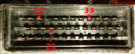
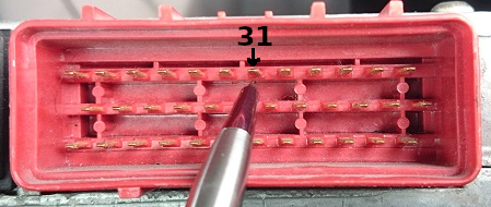
Looking at the ECU with black connector on the left and red connector on the right, and with the top plate (with a big X) facing up.
Black connector
Red connector
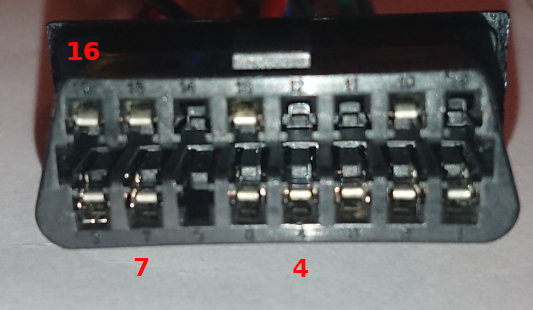
16 pin diagnostic connector
Black connector:-
21 (middle row, fourth pin from left): 0V
27 (top row, third pin from left): 12V
33 (top row, ninth pin from left): 12V
Red connector:-
31 (top row, seventh pin from left): K-line
Diagnostic socket:-
4: 0V
7: K-line
16: 12V
Please be careful !
by pscan.uk
The following user(s) said Thank You: sworkscooper
Please Log in or Create an account to join the conversation.
by pscan.uk
The following user(s) said Thank You: sworkscooper
Please Log in or Create an account to join the conversation.
Hi! I've double checked the wiring diagrams - everything was fine  - and connected the Ecu, the Pscan and the battery.
The result is that the K line fault message is not shown anymore. Instead it shows Wait for line to settle, then Attempting fast Init and then asks to switch off and on the Ignition - did this by disconnecting the positive from the battery - and lastly it shows the message Init fail.
I've also tried to reproduce the error by removing the K line cable, but the it shows the same sequence described above 🙄
Is this what you expected to happen? Anything else I should test? I think next thing is for me would be to understand what switching off and on the ignition means. Would it just mean unplugging the wire from pin 33?
Many many thanks for your help!
David
by David106
Please Log in or Create an account to join the conversation.
Pin 33 on the black connector is ignition switched power, so ignition on is pin 33 connected, ignition off is pin 33 disconnected.
There are already some conclusions from your experiments:-
Conclusion 1:
When you connect pscan to your car it says K line fault, but on your table it does not. On your car there is a simple wire directly from pin 7 of the OBD socket to pin 31 of the red ECU connector. It should not go anywhere else. K line fault means that this wire must be shorted to something else. You need to trace this wire from the OBD connector to the ECU and see if it damaged, or if someone has modified the wiring.
This is important because if the pins on the OBD connector are connected to the wrong things then this could damage the pscan interface.
Conclusion 2:
If appears that your MEMS2J ECU may be damaged, or I have made a mistake with my instructions. When the ECU is powered on I would expect to find 5 volts on some of the sensor pins. Unfortunately I do not have access to my MEMS2J for about one week.
Please also check that pin 13 of the OBD connector goes only to the SRS ECU.
by pscan.uk
Please Log in or Create an account to join the conversation.
Moderators: pscan.uk
Time to create page: 0.560 seconds


