
MGF Bonnet Gas Strut

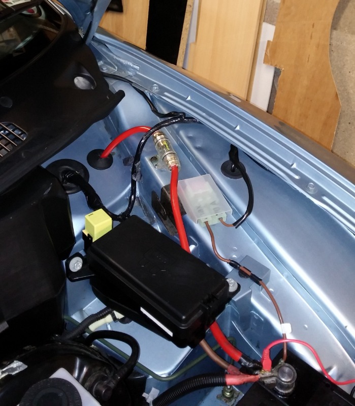
For some while I've been thinking about the idea of fitting a gas strut, or struts, to the bonnet. Having done a little online research I found there was a "2-strut" version on the T-Bar forum; it didn't appeal to me because it needed some metal bashing of the bonnet inner skin to make it fit.There was a "1-strut" version in an article in FasTForward in Autumn 2011 which appealed more, although it described the installation of a strut kit which is no longer available. Nevertheless I thought there was enough in the text and pictures to make my own. The following describes my design. First step is to acquire a gas strut. The length needed is 600mm, with stroke of 250mm, and my local breakers had dozens available, all around £10. Not knowing what compression force I needed, I chose one from a Ford Puma, which, testing on the bathroom scales, had a 20kg force. In the event this wasn't enough and I subsequently used one from a Ford Fiesta 3 with a 34kg force. Two 10mm ball end M8 studs will also be needed (£3 from ebay). Obviously the geometry of the strut and fittings was critical, both in terms of achieving the same bonnet opening as before and also in ensuring there was clearance for the compressed strut and that it didn't 'bottom out' when the bonnet was closed. To achieve a clear path for the strut some repositioning of components was necessary. I removed the EPAS fuse holder from its original position, Pic 1, by drilling out one rivet from what can only be described as a "horrible rusty bracket", goodness knows why it was designed like this! Then unscrew this bracket and discard, but keep the screw. Next, lever out the brown power feed wire plastic support from its mounting, also Pic 1, and remove the plastic support; it's only attached with insulating tape.
Picture 1
Picture 2
Picture 3
Picture 4
Picture 5
Picture 6
Picture 7
Picture 8
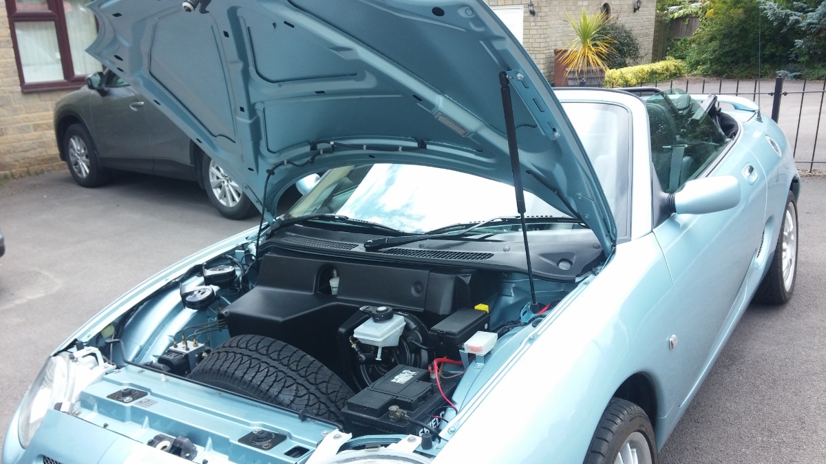
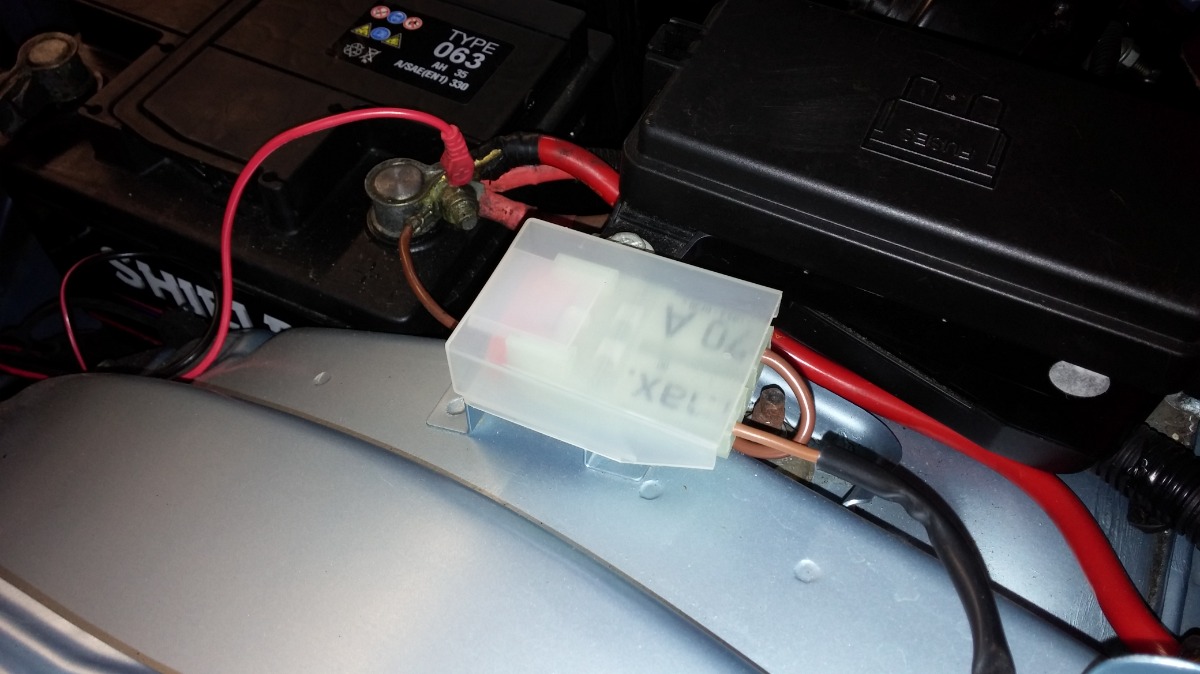
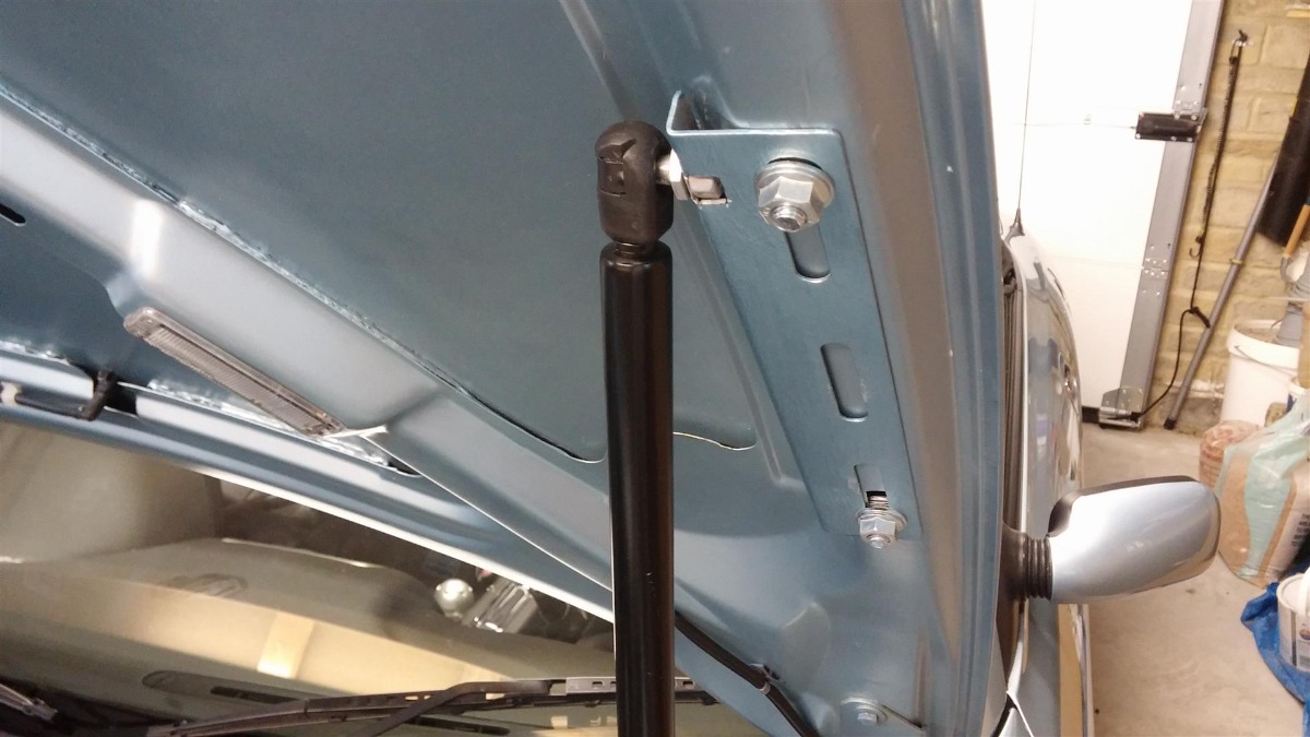
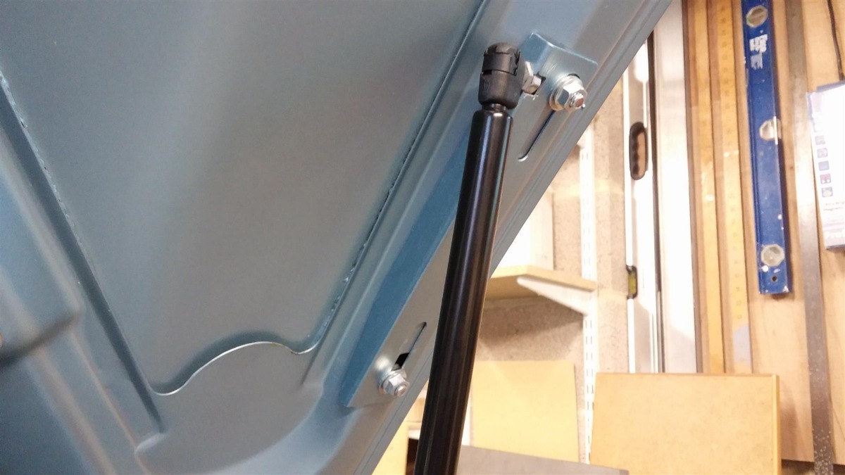
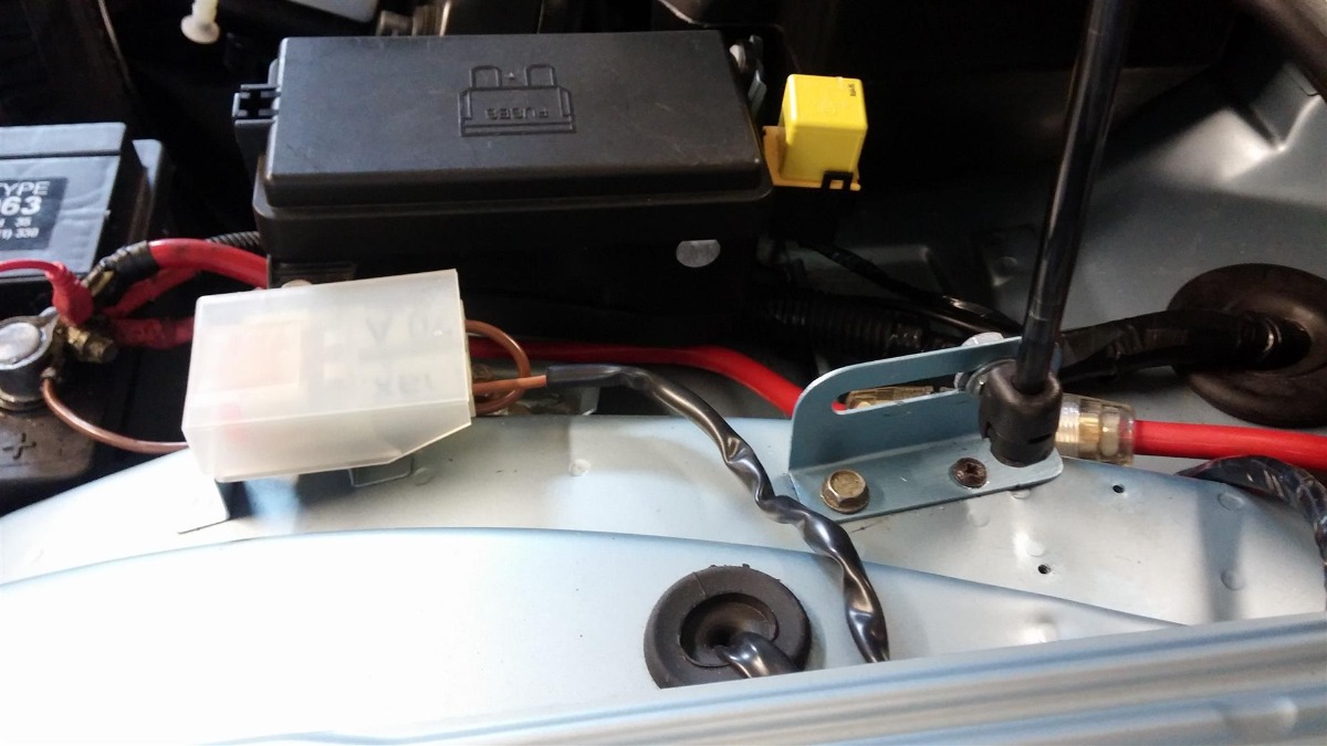
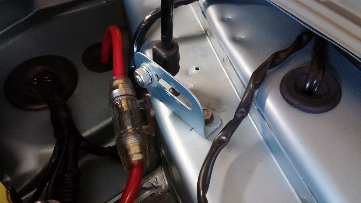
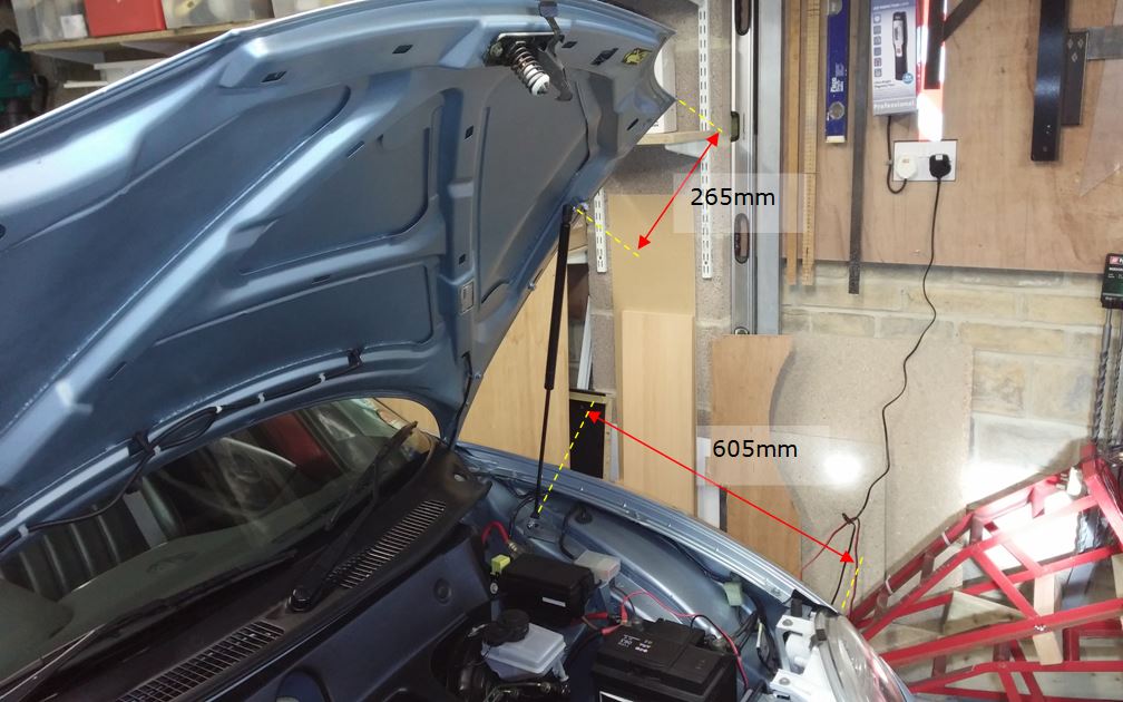
Now, I rotated the EPAS fuse holder through 180° and reattached it adjacent to the black main fuse box. Unfortunately I couldn't use the hole just vacated by the brown wire support, so drilled a new hole to give sufficient clearance and screwed the holder in with a self tapper. The brown wire is just long enough to re-route under the existing bracket and come in from the other side, Pic 2. Ensure it is protected from vibration and sharp edges. The strut brackets were made from pieces of plated steel angle strip I had available. The top bracket I made long enough to attach using the 2 convenient holes in the nearside bonnet stiffener, Pic 3. I used a couple of M8 x 15mm dome head screws and filed a small flat to joggle them into the holes, with 2 rectangular steel washers to fit inside. It's a little fiddly and you need to be careful not to let the screw fall into the hole! I clamped mine temporarily using mini locking pliers. Ideally the bracket needs to be wide enough so that the ball end stud nut doesn't foul the bonnet skin. I had to cut a recess to get mine to fit, as shown in Pic 4. Next I constructed the bottom bracket and fitted it to the box section where the old "horrible rusty bracket" had attached. My bracket had a convenient slot to allow for adjustment. I used the existing hole and captive nut to fix it, and for additional strength drilled a new hole for a self tap screw, see Pics 5 and 6. It is important to align this bracket with the plane of strut rotation as it closes. I've shown some key dimensions from my installation for positioning the strut, Pic 7. I've chosen to relate the ball end stud hole centres to the bonnet 'corner' and mating wing position. Incidentally, for those wondering what the heavy red cable and inline fuse is, it feeds power to an Infinity Kappa amplifier in the boot - not my choice! That's it, and I'm very pleased with the result, Pic 8. Don't forget to 'add lightness' by removing the redundant bonnet stay!
Picture 1
Picture 2
Picture 3
Picture 4
Picture 5
Picture 6
Picture 7
Picture 8
Now, I rotated the EPAS fuse holder through 180° and reattached it adjacent to the black main fuse box. Unfortunately I couldn't use the hole just vacated by the brown wire support, so drilled a new hole to give sufficient clearance and screwed the holder in with a self tapper. The brown wire is just long enough to re-route under the existing bracket and come in from the other side, Pic 2. Ensure it is protected from vibration and sharp edges. The strut brackets were made from pieces of plated steel angle strip I had available. The top bracket I made long enough to attach using the 2 convenient holes in the nearside bonnet stiffener, Pic 3. I used a couple of M8 x 15mm dome head screws and filed a small flat to joggle them into the holes, with 2 rectangular steel washers to fit inside. It's a little fiddly and you need to be careful not to let the screw fall into the hole! I clamped mine temporarily using mini locking pliers. Ideally the bracket needs to be wide enough so that the ball end stud nut doesn't foul the bonnet skin. I had to cut a recess to get mine to fit, as shown in Pic 4. Next I constructed the bottom bracket and fitted it to the box section where the old "horrible rusty bracket" had attached. My bracket had a convenient slot to allow for adjustment. I used the existing hole and captive nut to fix it, and for additional strength drilled a new hole for a self tap screw, see Pics 5 and 6. It is important to align this bracket with the plane of strut rotation as it closes. I've shown some key dimensions from my installation for positioning the strut, Pic 7. I've chosen to relate the ball end stud hole centres to the bonnet 'corner' and mating wing position. Incidentally, for those wondering what the heavy red cable and inline fuse is, it feeds power to an Infinity Kappa amplifier in the boot - not my choice! That's it, and I'm very pleased with the result, Pic 8. Don't forget to 'add lightness' by removing the redundant bonnet stay!
Last Edit:1 year 2 months ago
by wedgewood
Last edit: 1 year 2 months ago by Roverlike. Reason: Pic1 added
The following user(s) said Thank You: David Aiketgate, TA22GT
Please Log in or Create an account to join the conversation.

Thank you.
Very detailed info and pics and the strut obviously works!
Very detailed info and pics and the strut obviously works!
by TA22GT
Please Log in or Create an account to join the conversation.
Due to my lack of IT skills this article has not appeared where I wanted it - in the "How to Guides"! But I can't see how to edit it or move it, maybe a Moderator can help? Also, there is one photo missing, Pic 1, which only shows the EPAS holder as it was positioned originally, before I started the modification. I'll try and add the missing Pic 1.

I'm happy to answer any points or queries, but just to say, the gas strut has worked fine for 10 years!
I'm happy to answer any points or queries, but just to say, the gas strut has worked fine for 10 years!
by wedgewood
Please Log in or Create an account to join the conversation.


I added picture 1 in original first post, named pictures, made slight space between pictures and moved topic to How tos.
by Roverlike
Please Log in or Create an account to join the conversation.
- Airportable
-
 Offline
- Master MGer
-

Site Supporter
- Posts: 3675
- Thanks: 912
Bonnet picture 1
Bonnet picture 2
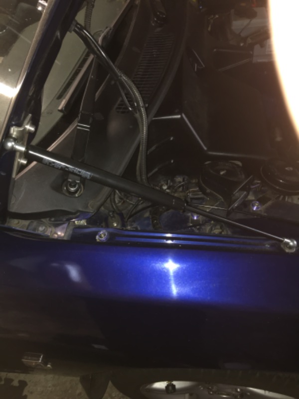
Bonnet picture 3
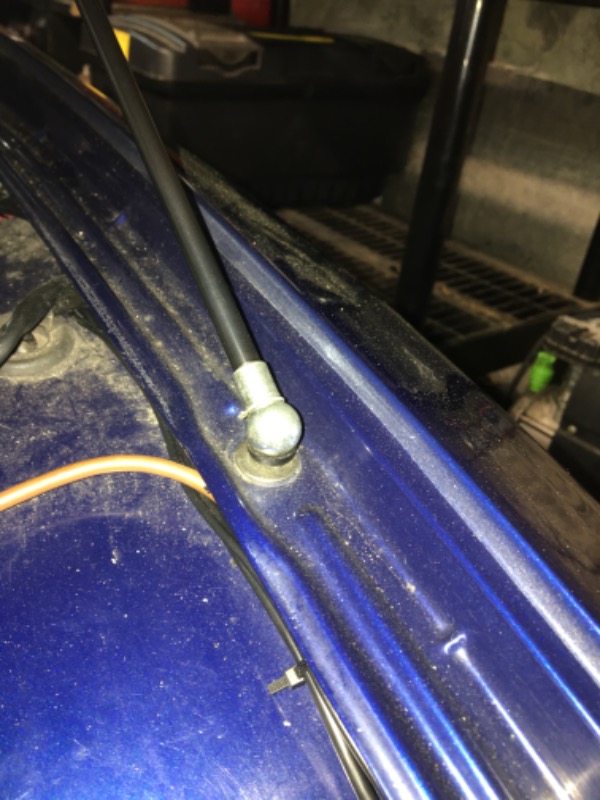
Boot picture 4
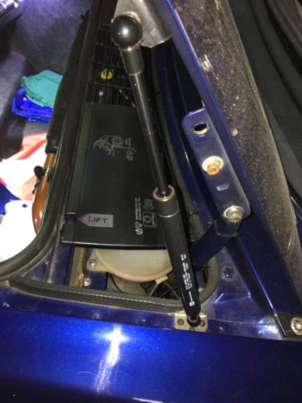
I do enjoy reading about the practical projects undertaken by other members, especially if I’ve taken the same road.
Wedgewood has found a way to fit struts without the extra layer engineering that my system adopted & this system has worked for ten years. It’s obvious a good job.
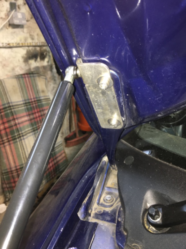
Initial I fabricated the two bracket, this was far from satisfactory & I ultimately had them laser cut & bent professionally.
On my iteration I used existing fixing points, managing to fit the bracket without comprising adjustments & overall operations.
I have some rather poor photographs that I’ll include.
Bonnet picture 2
Bonnet picture 3
Boot picture 4
I do enjoy reading about the practical projects undertaken by other members, especially if I’ve taken the same road.
Wedgewood has found a way to fit struts without the extra layer engineering that my system adopted & this system has worked for ten years. It’s obvious a good job.
Initial I fabricated the two bracket, this was far from satisfactory & I ultimately had them laser cut & bent professionally.
On my iteration I used existing fixing points, managing to fit the bracket without comprising adjustments & overall operations.
I have some rather poor photographs that I’ll include.
Last Edit:1 year 2 months ago
by Airportable
Last edit: 1 year 2 months ago by Roverlike.
The following user(s) said Thank You: Red110
Please Log in or Create an account to join the conversation.
- Airportable
-
Offline
- Master MGer
-
Site Supporter
- Posts: 3675
- Thanks: 912
One day I’ll affix pictures in the correct order, in the correct place within the text & in the correct number.
Sorry admin team, I’ll leave the layout to you. Thank you.
M
Sorry admin team, I’ll leave the layout to you. Thank you.
M
by Airportable
Please Log in or Create an account to join the conversation.
I fixed the layout of the pictures and added some caption for them.
by Roverlike
Please Log in or Create an account to join the conversation.
- Airportable
-
Offline
- Master MGer
-
Site Supporter
- Posts: 3675
- Thanks: 912
Thank you so much, your skills cross continents.
M
M
by Airportable
Please Log in or Create an account to join the conversation.
That's really neat AP and the brackets look really good.
by TA22GT
Please Log in or Create an account to join the conversation.
- Airportable
-
Offline
- Master MGer
-
Site Supporter
- Posts: 3675
- Thanks: 912
Neatness & good were not descriptors of first fabricated failures. The geometry was about right on one side & not at all on the other. No amount of grinding & filing made them anything other than crap; they made a satisfying noise as they were thrown in the scrap bin.
M
M
by Airportable
Please Log in or Create an account to join the conversation.
Time to create page: 0.410 seconds