
Adding Spotlights to MGTF - wiring help needed pretty please!
- Airportable
-
 Offline
- Master MGer
-

Site Supporter
- Posts: 3675
- Thanks: 912
Replied by Airportable on topic Adding Spotlights to MGTF - wiring help needed pretty please!
Posted 1 year 8 months ago #209522M
Please Log in or Create an account to join the conversation.


Replied by Cobber on topic Adding Spotlights to MGTF - wiring help needed pretty please!
Posted 1 year 8 months ago #209527"Keep calm, relax, focus on the problem & PULL THE BLOODY TRIGGER"
Please Log in or Create an account to join the conversation.


Replied by Malakite on topic Adding Spotlights to MGTF - wiring help needed pretty please!
Posted 1 year 4 months ago #211975The weather is picking up now and so I am looking at getting back out on the car as it's a big project... I am still non the wiser of what wires I should be piggy backing into...it's so frustrating and the car has just been say with the console hanging out

I am ultimately unsure what coloured wires on the main loom in the car are that I should be connecting to with the ones remaining from the kit that I purchased.
I shall take a couple of new pictures to hopefully show you all a little easier with what is left.... I had hoped the so called 'instructions' I posted up that came with the kit, together with the additional wiring diagrams for teh back of the green plug that goes into the back of the fog light switch, may have helped with the situation, but in all honesty they clearly havent!
SO frustrated by it all and sorry if I have caused you all stress with asking so many questions
I will be able to post pictures up tomorrow - thanks ever so much once again...
Please Log in or Create an account to join the conversation.
Replied by Malakite on topic Adding Spotlights to MGTF - wiring help needed pretty please!
Posted 1 year 4 months ago #212026Part 1:
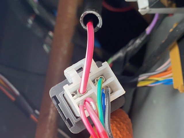
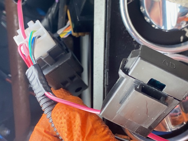
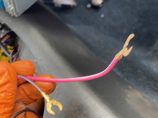
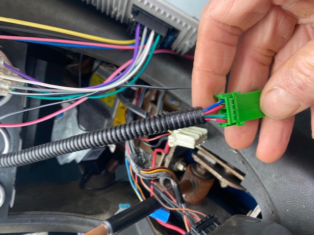
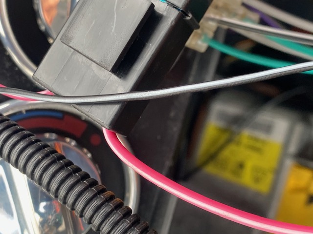
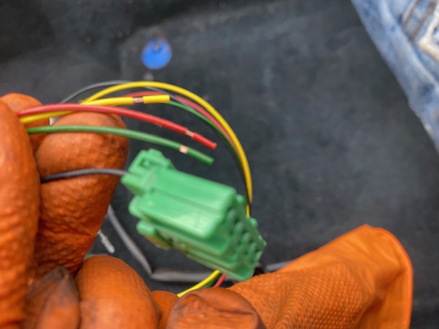
So you will see from the first couple pictures, that the loom from the front lights that I purchased, comes through with just one red wire, that goes into the block connector part of the switch/transistor, which in turn, has a series of wires coming out from it, of which (pink & white) goes into the inline fuse, and out the other side with a copper "C-shaped" connector on the end. The other with with a Copper "C-shaped" connector, comes from the back of the switch/transistor unit that the other come out from....together with a cluster of other wires from the same switch/transistor that come down to a small green connector..
Please Log in or Create an account to join the conversation.
Replied by Malakite on topic Adding Spotlights to MGTF - wiring help needed pretty please!
Posted 1 year 4 months ago #212027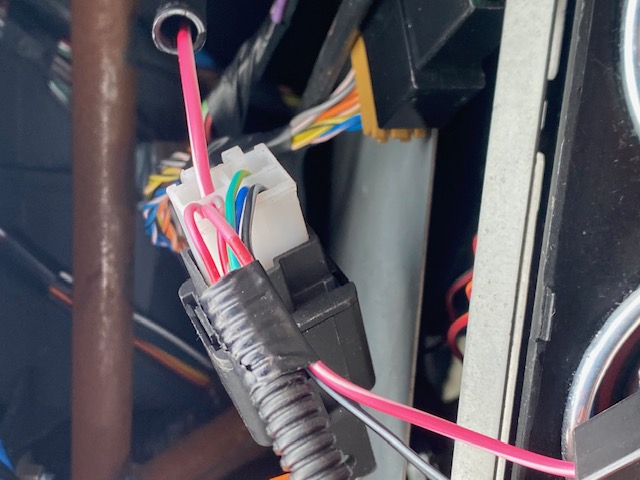
Please Log in or Create an account to join the conversation.
Replied by Malakite on topic Adding Spotlights to MGTF - wiring help needed pretty please!
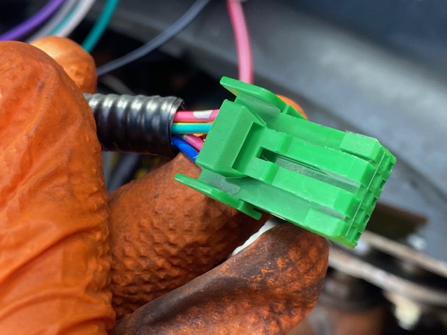
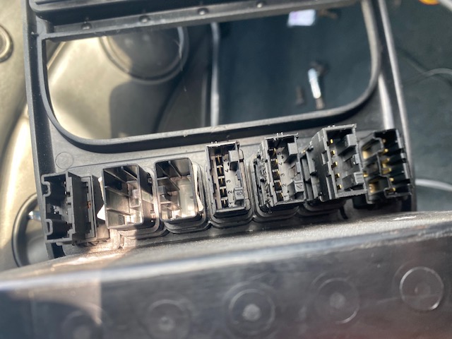
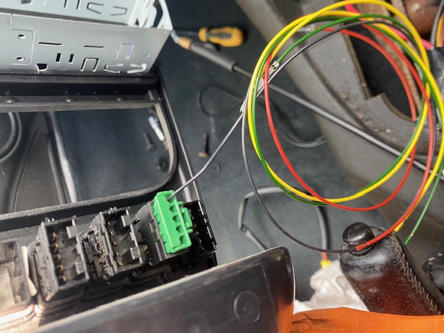
Posted 1 year 4 months ago #212029So as you can see from these attached pictures - the worse that go into the end "smaller" green connector that came as you see in the pic, I feel should go directly into the back of the front light switch - I have noticed however, that the connector is too small, and so I am wondering if the additional connector and wires that came with the kit, are for this very purpose? In which case, I would need help in working out what coloured wires went in what order (if that even matters?) into the back of the larger green connector, which I have checked DOES fit directly into the back of the front fog switch unit itself. So I either cut the smaller green connector and just joining the wires together, OR see if there is a compatible unit that joins both the connectors together... any ideas?!
I notice that going into the small connector, we have 2 X pink & silver wires, 1 X Blue and 1 X Green and yellow... whereas the wires supplied for the larger connector, are 1 X Black, 1 X Yellow, 1 X Red & ! X green... at least I have the same AMOUNT of matching wires lol.. also so I presume that it doesn't mater what colour I connect to them, so long as I get the correct order of wires into the back of the larger green connector? In which case, how would I know what wire is what? in the first place that go into the smaller green connector from the loom??
Goodness I do really hope that this all makes sense to you ...

Please Log in or Create an account to join the conversation.


Replied by Roverlike on topic Adding Spotlights to MGTF - wiring help needed pretty please!
Posted 1 year 4 months ago #212033However, I will put one disclamer here: I am doing this by keyboard and I am not present with you so if I misunderstood something it is not intentional and if something is connected wrong, since I am not there with you to test it I cannot help and I cannot be taken as responsible for any problem. I am trying to help in good will, but I am few thousand miles away from you.
What you call switch/transistor with one red/white wire going into and bunch of wires coming out is plain normaly open relay.
What we do not see in all pictures is Blue/Black wire which is earth coming from lamps. In seller description that is lamps earth and if that is not connected to firm earth point lamps will not work.
Small green connector with 4 wires is, by explanantion of the seller, connector of generic switch which you will not use at all (so you can forget about it).
Red/White wire with "C-shaped" connector which goes to in-line fuse is power wire for the fog lamps. That wire needs to be connected to car battery or any strong power point with large fuse capable to power front fog lamps - in accordance to seller.
Black/Grey wire with "C-shaped" connector is earth wire for above mentioned relay trigger coil (trigger circuit in accordance to seller). That connector needs to be connected to nearest earth point. Since I am not with you in car I cannot point you where to connect it at this moment.
Now we come to the switch. My problem is that explanation provided from seller on swith connector pinout is not the correct one as I see it. From my understanding pinout should be:
Pin 1: Power feed used for tell tale illumination and when switch is pressed make continuation to pin number 4
Pin 2: Night time illumination feed
Pin 3: Not used
Pin 4: Relay power feed for trigger coil
Pin 5: Earth
Difference from seller is swap of pins 4 and 5, and then pins 4 and 1.
You are provided with 4 wires of different colours. Which wire colour you will put in poisitions 1, 2, 4 and 5 is not important, but it is important where you connect wires which comes from each pin.
Now, what seller described in his installation guide is for you to piggy pack wires from new switch to rear fogs blue connector. Note that his explanation differes from my above connecotr pinout for pins 4 and 5 and then pins 4 and 1.
Problem is, if you connect as seller suggested - piggy pack to rear fogs switch connector, then you will be able to power front fogs only when rear fogs are powered. Note that rear fogs can be powered only in case when lights are on. If you are fine with this we can continue to explain you what to do. If not then we need to find another solution, and create different pinout (for example use night illumination power for relay trigger coli).
i would like one big thing to be done, that is, your front fogs switch to be tested and see if pinout is assumed correctly - do pin 1 has continuation to pin 4 when switch is pressed, and will switch lights glow when power is applied to described pins. Without this test we are guessing and problems might occure if we assumed wrong.
Please Log in or Create an account to join the conversation.
Replied by Cobber on topic Adding Spotlights to MGTF - wiring help needed pretty please!
Posted 1 year 4 months ago #212046Given that this has taken so long to resolve and we still seem to be going in ever diminishing circles, I suspect we will continue to be trapped in this spiral, unless you seek the services of an auto electrician. A competent auto electrician should be able to sort this out pretty quickly.
They will physically be able to see and test to establish what goes where, alas the best we can do remotely with out being able to confirm things with a multimeter of test light is guess.
Our problem stems from the seller of the kit and the fact that they are long gone from the scene, they appear to have used random wire colours (probably whatever they had laying about) and have provided two switch plugs, so as to allow for both early and later type switches without troubling themselves with a explanation of what goes where.
Unfortunately my tame auto electrician has been scarce over the last few months as he has been off traveling so I've been unable to consult with him on this matter, i can't even consult with him over the internet as he is very old school and isn't really computer literate (he normally relies on me to help him deal with matters on the net)
Like I've said previously this would be easy to sort out in person, but there are variables to contend with and at distance this only adds to all of our mutual confusion.
Where abouts are you? maybe if someone is close by they might be kind enough to have a look.
"Keep calm, relax, focus on the problem & PULL THE BLOODY TRIGGER"
Please Log in or Create an account to join the conversation.
Replied by Malakite on topic Adding Spotlights to MGTF - wiring help needed pretty please!
Posted 1 year 4 months ago #212048What you call switch/transistor with one red/white wire going into and bunch of wires coming out is plain normaly open relay. (ok)
What we do not see in all pictures is Blue/Black wire which is earth coming from lamps. In seller description that is lamps earth and if that is not connected to firm earth point lamps will not work. (pics from an older post of mine show a blue wire from the fogs which also has the 'C-shaped' connector, under the bonnet - I shall make sure this is grounded then
)Small green connector with 4 wires is, by explanantion of the seller, connector of generic switch which you will not use at all (so you can forget about it). (OK. But do I not need to connect the larger correct fitting green connector, so the wires that are going into the smaller one, as these come from the 'relay' loom?)
Red/White wire with "C-shaped" connector which goes to in-line fuse is power wire for the fog lamps. That wire needs to be connected to car battery or any strong power point with large fuse capable to power front fog lamps - in accordance to seller. (Do you have any suggestions? I'd need to massively extend this back if going directly to the battery, and if I did - does it need an additional fuse, or otherwise do you have any suggestions as to where I could fix it to i.e. another wiring loom under the dash?)
Black/Grey wire with "C-shaped" connector is earth wire for above mentioned relay trigger coil (trigger circuit in accordance to seller). That connector needs to be connected to nearest earth point. Since I am not with you in car I cannot point you where to connect it at this moment. (ok so I can always earth that to any part of the car then??..)
Now we come to the switch. My problem is that explanation provided from seller on swith connector pinout is not the correct one as I see it. From my understanding pinout should be:
Pin 1: Power feed used for tell tale illumination and when switch is pressed make continuation to pin number 4
Pin 2: Night time illumination feed
Pin 3: Not used
Pin 4: Relay power feed for trigger coil
Pin 5: Earth
Difference from seller is swap of pins 4 and 5, and then pins 4 and 1.
You are provided with 4 wires of different colours. Which wire colour you will put in poisitions 1, 2, 4 and 5 is not important, but it is important where you connect wires which comes from each pin.
Now, what seller described in his installation guide is for you to piggy pack wires from new switch to rear fogs blue connector. Note that his explanation differes from my above connecotr pinout for pins 4 and 5 and then pins 4 and 1.
Problem is, if you connect as seller suggested - piggy pack to rear fogs switch connector, then you will be able to power front fogs only when rear fogs are powered. Note that rear fogs can be powered only in case when lights are on. If you are fine with this we can continue to explain you what to do. If not then we need to find another solution, and create different pinout (for example use night illumination power for relay trigger coli). (OK - I think the latter is the best option as it would be good to have the switch light up, and be able to use the front fogs whenever I wanted, separate from the rears...)
i would like one big thing to be done, that is, your front fogs switch to be tested and see if pinout is assumed correctly - do pin 1 has continuation to pin 4 when switch is pressed, and will switch lights glow when power is applied to described pins. Without this test we are guessing and problems might occure if we assumed wrong. (OK - what may I ask, is the best way of testing that? So sorry to be so dumb when it comes to electrics!) I have a standard current light/screwdriver, and also a multimeter, although the latter is not with me at the moment it's 3 hours drive away!)
Please Log in or Create an account to join the conversation.
Replied by Malakite on topic Adding Spotlights to MGTF - wiring help needed pretty please!
Posted 1 year 4 months ago #212049Please Log in or Create an account to join the conversation.
Replied by Cobber on topic Adding Spotlights to MGTF - wiring help needed pretty please!
Posted 1 year 4 months ago #212050Right well as I'm in Australia, forgive me when I say that I'm not likely to be popping in, to help you out, anytime soon!G'day Cobber! I am in England!
However if you were to further enlighten us as to what county, city/town/suburb you are in? Then maybe one of the other members who is local to you, might take pity on you and offer to have a look.
"Keep calm, relax, focus on the problem & PULL THE BLOODY TRIGGER"
Please Log in or Create an account to join the conversation.
Replied by Roverlike on topic Adding Spotlights to MGTF - wiring help needed pretty please!
Posted 1 year 4 months ago #212053Reply is in GREEN.Hello Roverlike kind sir - this is great thank you so so much for your response... I honestly can't thank you enough for your help and patience here.. So here are my responses to your post (in red italics) to hopefully make things a little easier!
What you call switch/transistor with one red/white wire going into and bunch of wires coming out is plain normaly open relay. (ok)
What we do not see in all pictures is Blue/Black wire which is earth coming from lamps. In seller description that is lamps earth and if that is not connected to firm earth point lamps will not work. (pics from an older post of mine show a blue wire from the fogs which also has the 'C-shaped' connector, under the bonnet - I shall make sure this is grounded then
Small green connector with 4 wires is, by explanantion of the seller, connector of generic switch which you will not use at all (so you can forget about it). (OK. But do I not need to connect the larger correct fitting green connector, so the wires that are going into the smaller one, as these come from the 'relay' loom?)
Red/White wire with "C-shaped" connector which goes to in-line fuse is power wire for the fog lamps. That wire needs to be connected to car battery or any strong power point with large fuse capable to power front fog lamps - in accordance to seller. (Do you have any suggestions? I'd need to massively extend this back if going directly to the battery, and if I did - does it need an additional fuse, or otherwise do you have any suggestions as to where I could fix it to i.e. another wiring loom under the dash?)
Black/Grey wire with "C-shaped" connector is earth wire for above mentioned relay trigger coil (trigger circuit in accordance to seller). That connector needs to be connected to nearest earth point. Since I am not with you in car I cannot point you where to connect it at this moment. (ok so I can always earth that to any part of the car then??..)
Now we come to the switch. My problem is that explanation provided from seller on swith connector pinout is not the correct one as I see it. From my understanding pinout should be:
Pin 1: Power feed used for tell tale illumination and when switch is pressed make continuation to pin number 4
Pin 2: Night time illumination feed
Pin 3: Not used
Pin 4: Relay power feed for trigger coil
Pin 5: Earth
Difference from seller is swap of pins 4 and 5, and then pins 4 and 1.
You are provided with 4 wires of different colours. Which wire colour you will put in poisitions 1, 2, 4 and 5 is not important, but it is important where you connect wires which comes from each pin.
Now, what seller described in his installation guide is for you to piggy pack wires from new switch to rear fogs blue connector. Note that his explanation differes from my above connecotr pinout for pins 4 and 5 and then pins 4 and 1.
Problem is, if you connect as seller suggested - piggy pack to rear fogs switch connector, then you will be able to power front fogs only when rear fogs are powered. Note that rear fogs can be powered only in case when lights are on. If you are fine with this we can continue to explain you what to do. If not then we need to find another solution, and create different pinout (for example use night illumination power for relay trigger coli). (OK - I think the latter is the best option as it would be good to have the switch light up, and be able to use the front fogs whenever I wanted, separate from the rears...)
i would like one big thing to be done, that is, your front fogs switch to be tested and see if pinout is assumed correctly - do pin 1 has continuation to pin 4 when switch is pressed, and will switch lights glow when power is applied to described pins. Without this test we are guessing and problems might occure if we assumed wrong. (OK - what may I ask, is the best way of testing that? So sorry to be so dumb when it comes to electrics!) I have a standard current light/screwdriver, and also a multimeter, although the latter is not with me at the moment it's 3 hours drive away!
Small green connector with 4 wires is, by explanantion of the seller, connector of generic switch which you will not use at all (so you can forget about it). (OK. But do I not need to connect the larger correct fitting green connector, so the wires that are going into the smaller one, as these come from the 'relay' loom?) This small green connector and its wires coming from relay are/will be parallel surplus to your larger correct fitting green connector when all its new wires are connected to appropriate places.
Red/White wire with "C-shaped" connector which goes to in-line fuse is power wire for the fog lamps. That wire needs to be connected to car battery or any strong power point with large fuse capable to power front fog lamps - in accordance to seller. (Do you have any suggestions? I'd need to massively extend this back if going directly to the battery, and if I did - does it need an additional fuse, or otherwise do you have any suggestions as to where I could fix it to i.e. another wiring loom under the dash?) Good alternative is fuse box under steering wheel. You cannot tap it to existing loom because power load of fog lamps can be too much and we do not want to make fire. I do not know which fusebox you have - meaning is your car MG TF mk1 or mk2. Picture of your fusebox under steering wheel would be good.
Black/Grey wire with "C-shaped" connector is earth wire for above mentioned relay trigger coil (trigger circuit in accordance to seller). That connector needs to be connected to nearest earth point. Since I am not with you in car I cannot point you where to connect it at this moment. (ok so I can always earth that to any part of the car then??..) You can earth it to any part of the car, BUT that part of the car must not have any paint on it, since paint is isolator. You need bare metal. Good point is again in fusebox under steering wheel.
i would like one big thing to be done, that is, your front fogs switch to be tested and see if pinout is assumed correctly - do pin 1 has continuation to pin 4 when switch is pressed, and will switch lights glow when power is applied to described pins. Without this test we are guessing and problems might occure if we assumed wrong. (OK - what may I ask, is the best way of testing that? So sorry to be so dumb when it comes to electrics!) I have a standard current light/screwdriver, and also a multimeter, although the latter is not with me at the moment it's 3 hours drive away!) For this you need a multimeter, but if you are not good with it, better to find someone who is to make these tests.
Please Log in or Create an account to join the conversation.